Overview
- Reinforced FDM 3D Printing is a derivative technology of standard FDM printing. The primary difference between FDM and reinforced FDM is that the base material (Nylon) is always infused with chopped carbon fiber, AND parts may contain continuous bands of carbon fiber within the X-Y plane during deposition.
- Please visit the manufacturer's website for further explanation of the technology and it's applications.
TEAM Lab Hardware
Markforged Mark II

Build Volume: 320x132x154mm
Max Extruder Temperature: 300°C
Layer Resolution: 100, 120, or 200 microns
Tolerance (deviation from intended value): ~150 microns
Filaments: "Onyx" (chopped-carbon fiber infused nylon), with optional continuous bands of carbon fiber, or Kevlar, or fiberglass)
Unique Properties:
- Carbon-fiber reinforced prints permit mechanical performance similar to that of a machined aluminum part (in XY plane, depending on amount of fiber reinforcement).
Materials
Onyx
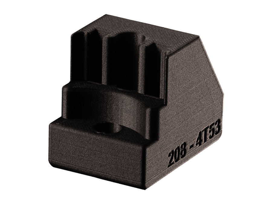
"Onyx" (by Markforged) is a proprietary composite material combining nylon with chopped carbon fibers. It is designed for high-performance applications where strength, toughness, and heat resistance are required.
Onyx is known for its superior surface finish, stiffness, and durability compared to traditional FDM printed plastics, making it applicable for high-stress mechanical applications, including jigs, fixtures, and functional prototypes.
The material is also compatible with Markforged's continuous fiber reinforcement technology, allowing parts printed with Onyx to be reinforced with materials like carbon fiber, Kevlar, or fiberglass for added strength and durability.
+Fiber Reinforcement
Unique to Markforged printers is the ability to strengthen prints by way of continuous bands of carbon fiber, embedded inside of a print. This is an optional material used in conjuction with "Onyx"
Optional strands of 0.12mm diameter filament:
- Carbon Fiber (our preference)
- Kevlar
- Fiberglass
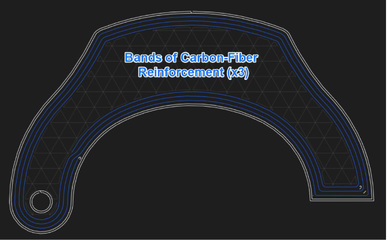
- The graphic bellow illustrates an XY cross-section of a fiber-reinforced part; Reinforcement bands are shown in blue.
Comparison to other printing technologies
Contrasted with Standard FDM
Reinforced FDM operates similarly to standard FDM printing but incorporates continuous strands of fiber filament to enhance stiffness and strength. However, unlike standard FDM, reinforced FDM does not support multi-material printing.
Contrasted with SLA or MSLA (Resin Printing)
Compared to SLA printing, Reinforced FDM parts have limitations in shape complexity but are generally far stronger and slightly more cost-effective. Resin-based printing methods, such as SLA and MSLA, produce smooth, solid, non-porous parts, which are critical for applications requiring sterility and interaction with liquids.
Contrasted with Polyjet
Reinforced FDM parts are significantly stronger and more cost-effective than those produced with PolyJet printing. However, they are also less accurate and more limited in shape complexity. Additionally, PolyJet printing produces solid, non-porous parts, making it ideal for applications involving liquid interaction (but not typically sterile applications due to absence of sterilization protocol).
Contrasted with DLP (Microfluidic Printing)
Our DLP 3D printer is optimized for microfluidic applications, where precision, clarity, and smooth surface finish are essential. Reinforced FDM printing is poorly suited for this purpose due to surface porosity, part opacity, and surface roughness. These two technologies serve very different applications with minimal overlap.
Examples:
example images courtesy of Markforged


Reinforced FDM Gallery
Click here to view more example Reinforced FDM prints.
Rates
- Note: We strongly recommend submitting a service request to obtain an accurate project cost estimate. Self-quoting can often lead to miscalculations
- Already have a quote from another vendor? Share it with us and we'll match or beat it.
We bill for time and materials while using our Reinforced FDM printers. For time, we assess 0.5 hours of assisted time per-print tray plus an hourly rate for machine use. Maximizing tray capacity with your parts—whether identical or varied—significantly reduces per-unit part cost.
| Description | Internal | External | |
| Materials | Per-gram expense for all materials in-stock | $0.60/gram | $0.80/gram |
| Setup and Processing | 0.5 hours of our assisted rate ($119/hour) per tray (not object) | $59.50/tray | $80/tray |
| Hourly Use Rate | Expense per hour of machine use | $6/hour | $8/hour |
Estimating project cost should be left to TEAM, but here are some general project estimates that can guide in self-estimating:
| Relative Project Scale | Cost for First Batch of Parts, Typical Range | Cost for Additional Batch of Parts, Typical Range |
| Small | $80-$100 | $20-$50 |
| Medium | $100-200 | $50-$100 |
| Large | $200+ | $100+ |
| Extra Large | NA - Not currently supported | NA - Not currently supported |
*All declared values at internal rates, NUD = university required "Non-University Differential" added for external.
Optional Post Processing Services
Epoxy Coating
If your FDM print necessitates a smooth surface finish, we can clad your prints in an epoxy coating to fill in surface defects. We stock, and use Smooth-On XTC-3D:
Pros of Epoxy Coating FDM Parts:
- Smooth, high-gloss surface finish
- Seals off surface porosity (to enhance compatibility with liquid applications)
- Paintable
Cons of Epoxy Coating FDM Parts:
- Alterations to the part's dimensional accuracy
- Additional cost (labor and materials)
Supports removal
Generally, we will do our best to remove supports as part of our basic service. However, if printing a very complicated part (with difficult to access supports, or a large volume of supports), we may assess additional time to cover the cost of support removal OR provide the part with supports for you, the client, to remove.
Threaded holes
Threads are generally not directly printed onto parts, but are instead added as a secondary process by way of tapping. Exceptions may occur where two bodies are designed to couple/decouple by way of coarse threads. Other (superior) techniques for adding threads involve using threaded inserts (usually brass), or capturing a nut; Both of these techniques result in much more durable threads than a printed part alone.
Important note regarding threaded features
- If your project incorporates threads, please make us aware so that we can coach you through the options and find the best fit for your application.
Direct-Printed Threads:

- Above Figure: Coarse Threads on Two Printed Bodies (via MatterHackers)
Strategies for adding threads as a post-processed feature:

- Above Figure: Different Techniques for Adding Threads to a Printed Part. Tapping, Threaded Insert, Captured Nut (via Formlabs)
Preparing Files for Printing:
The team lab suggests two sets of files for each 3D printed part (where possible) – the original parametric model file (Solidworks/Inventor/Fusion360/etc), and a millimeter scale STL file (point-mesh file). Please include these files on your project request if possible.
Technical Details
Note
- Please see our page devoted to FDM printing for a general understanding of the core technology. All details below are specific to Reinforced FDM.
Designing for Reinforced FDM Printing:
As with standard FDM printing, overhanging features often necessitate the existence support structure
(made of build-material) which must often be mechanically removed. In this case, expect occasional
print defects in these locations (rough finish, occasionally drooping, etc). Through careful design, often
times support structure can be avoided (ideal scenario). Support structures are covered in more detail
below.
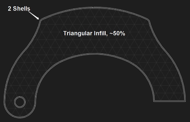
Hollow Prints
One important consideration for FDM prints – parts derived from this technology are
not solid; instead, they are generally created in a series of “shells” extending from the outside surface
inward, coupled with an “infill” to provide bulk-support. This process is achieved within the
printing/slicing software, not within CAD.
Above figure: 3D print cross-section, illustrating empty space inside part
Reinforcement Bands
To increase stiffness, and strength of parts, we often have the option of adding
strands of reinforcement fiber, planar to the build-axis during printing. As carbon-fiber is an expensive
resource, this action is typically limited to ~8 total layers, distributed across a part; however, more can be
added as necessary. Note that minimum wall thicknesses must be maintained in order to “fit” traces of
fiber reinforcement.
- Above figure: Depiction of 3D print cross-section, shown with bands of carbon-fiber reinforcement
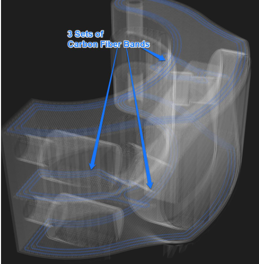
Above figure: Depiction of 3D print 3D view, shown with bands of carbon-fiber reinforcement
Get Started
- Heard enough? Get started with a service request! Your request need-not be perfect, we can always revise it as we go. Just provide us with as much detail as is necessary.
- Feeling overwhelmed with the options? We don't blame you! We do a lot! Feel free to email us to set up a consultation. We're happy to chat via zoom, or in person (where we can review samples).