Overview
- Our PCB manufacturing and assembly services may leverage both in-house, and external vendors working in support of your goals.
- In most instances (standard PCBs), we recommend use of a professional board house for PCB manufacturing. These boards are generally superior and less expensive. We are happy to work with external PCB manufacturers on your behalf.
- If your PCB has very specific material constraints, and you are willing and able to comply with our declared constraints (below), our on-site PCB manufacturing capabilities may be appropriate.
- In addition to manufacturing the PCB itself, we are also equipped with the tools and expertise to populate (assemble) your PCB.
- This service is often paired with our design services.
- PCBs may incorporate microcontrollers and programming where needed.
TEAM lab Hardware
LPKF USA Protomat S103

Working Envelope (maximum single PCB size): 229x305 mm (9 x 12 inches)
Materials: [Copper-clad] FR4, Polyamide, Teflon, Ceramic, Polyamide (PI), Epoxy
Substrate Compatibility: Rigid and Flex
Strategy: High-precision milling and drilling (subtractive)
Minimum Insulation Trace Width: 0.2mm
Minimum Hole Diameter: 0.3mm
Positioning Resolution: 0.5µm
Important Constraints
- This manufacturing platform does not support:
- Thru-hole Plating
- Surface Plating
- Vias
- Solder Resist Coatings
- Labels/Legends
- Instead, these features would need to be omitted, or accommodated in other ways (example: thru-hole plating and vias could be substituted for soldering elements on both sides)
Support Equipment


Materials
Our LPKF S103 is most appropriate in use cases where very specific materials are needed OR where a basic board is needed quickly. Below is a list of materials that can be used in conjunction with our in-house PCB mill.
- Copper-Clad FR4: This is generally what most PCBs are derived from; In instances where a very primitive (bare-copper board) is acceptable, and is needed quickly, our S103 may be a good fit.
- PTFE Substrates: Ideal for high-frequency applications, PTFE is often used in RF and microwave circuits.
- Rogers RO4000 Series: These materials are used for RF and microwave applications, containing ceramic particles to provide specific electrical properties.
- Flexible and Rigid-Flex PCBs: Made from polyimide films, the S103 can process these flexible substrates effectively, thanks to its high-speed spindle and optional vacuum table for secure handling.
- Ceramic Substrates: The ProtoMat S103 is capable of handling ceramics for RF applications, although LPKF's laser models are recommended for more delicate ceramics due to their non-contact processing.
- Thin Laminates: The high-capacity spindle and vacuum table also make the S103 suitable for thin laminate materials, especially those used in RF applications
Comparison between in-house, and external PCB manufacturing
- NOTE: TEAM can help you realize either of these two manufacturing routes.
In-House (Via TEAM)
Advantages:
- Potential for rapid turnaround (same day, or up to 3 days)
- Support for exotic substrates, or non-standard operations
Disadvantages:
- No plating (bare copper board)
- No masking
- No conductive vias
- No legends/labels
- More expensive
External (Via 3rd Party)
Advantages:
- Superior quality
- Inexpensive
Disadvantages:
- Roughly 1 week turnaround (slightly longer than manufacturing in-house)
Examples


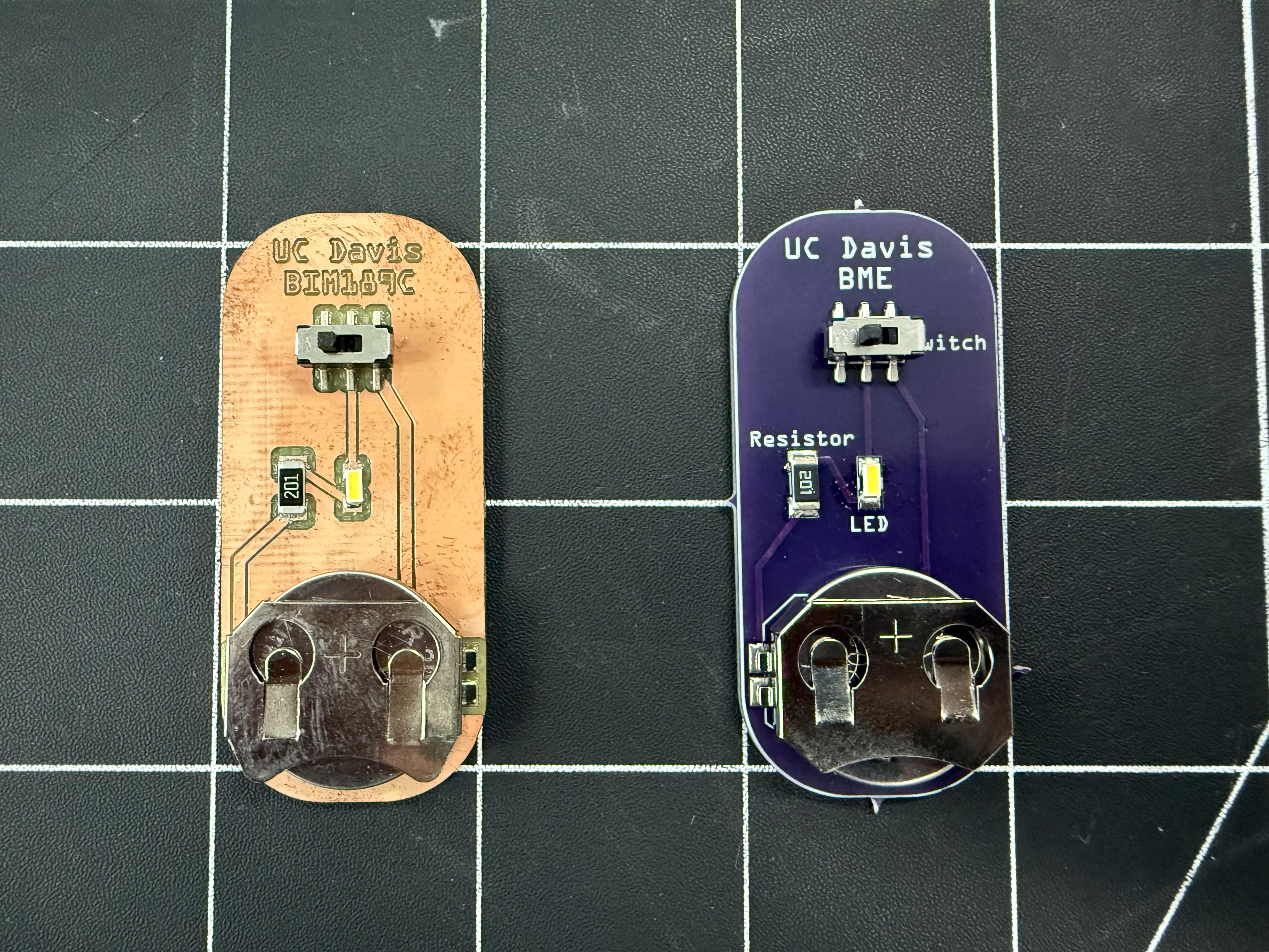

Printed Circuit Board (PCB) and Electronics Gallery
Click here to view more examples of PCBs and Electronics
Preparing Files for Manufacturing:
Assuming you have a deisgn ready for manufacturing (if not, we can help with this step), we would need your stack of gerber files (and or your original design CAD model) to complete manufacturing. Please work with the TEAM lab for more detailed instructions if this is unclear.
Technical details:
PCB Design Overview
Printed Circuit Board (PCB) design and manufacturing is an intricate and multifaceted process that draws on the principles of electronics, materials science, and precision engineering. The process begins with PCB design, wherein both the electronic layout and the physical structure of the board are meticulously conceptualized and refined. This phase initiates with the creation of a schematic, a graphical representation that defines the electrical interconnections between various components. Sophisticated Electronic Design Automation (EDA) software tools, such as Altium Designer, KiCad, and EAGLE, are employed to create the schematic, which is subsequently translated into a physical layout. This layout process involves careful optimization of component placement, signal routing, and thermal considerations to ensure electromagnetic compatibility (EMC) and system reliability.
Layout Design
During the layout design phase, the PCB is conceived in multiple layers, each incorporating conductive pathways, primarily copper, to establish the necessary electrical connections among components. Advanced tools such as Mentor Graphics PADS and Cadence Allegro are indispensable for managing the complexities associated with high-density, multilayer board designs. Designers rigorously apply a comprehensive set of design rules governing trace spacing, trace width, impedance control, and power distribution to maintain the electrical and thermal integrity of the system. A particular emphasis is placed on the integration of ground planes and power planes, which play a critical role in reducing electromagnetic interference (EMI), stabilizing reference voltages, and optimizing current flow.
Gerber File Generation and Substrate Preparation
Upon finalizing the layout, a series of Gerber files are generated, serving as the authoritative blueprint for PCB fabrication. These files contain precise details regarding each layer of the board, including copper traces, solder masks, silkscreen, and drilling information, ensuring that the physical board faithfully replicates the design intent. The manufacturing phase begins with substrate preparation, in which materials such as FR4 (a fiberglass-reinforced epoxy) or Rogers laminates are selected based on the application's electrical, thermal, and mechanical requirements. Photoengraving or laser etching technologies are employed to accurately transfer the intricate board layout onto the substrate, followed by a chemical etching process that removes excess copper, thereby delineating the desired circuit paths with high precision.
Drilling and Via Formation
Following substrate preparation, the board undergoes precision drilling to create apertures for vias and through-hole components, enabling inter-layer electrical connectivity. Advanced CAD/CAM tools such as CAM350 and Altium Designer are commonly used to generate NC drill files, which control automated drilling systems to ensure precise and accurate hole positioning. After drilling, the vias are subjected to an electroplating process, which metallizes the drilled holes to form conductive pathways between the various layers of the PCB. This step is crucial for maintaining signal integrity and ensuring robust inter-layer connectivity in multilayer designs.
Solder Mask, Silkscreen, and Surface Finish
The next stage involves the application of the solder mask, an insulating layer that covers the copper traces to prevent oxidation and mitigate the risk of short circuits during operation. The solder mask leaves exposed only those regions where components will be soldered. Following this, the silkscreen layer is applied, which provides essential information such as component identifiers, reference designators, and other assembly notes, thus facilitating ease of assembly and troubleshooting. To prepare the exposed copper pads for component soldering, surface finishes such as HASL (Hot Air Solder Leveling) or ENIG (Electroless Nickel Immersion Gold) are applied. These finishes are selected based on criteria such as solderability, environmental resistance, and the intended application of the PCB.
Assembly Process
In the assembly process, the PCB is populated with electronic components using either Surface Mount Technology (SMT) or Through-Hole Technology (THT). SMT is predominantly favored in modern electronics due to its ability to accommodate high component density, thus enabling more compact designs. Pick-and-place machines are programmed to accurately position components based on design data, and once positioned, the board passes through a reflow oven to securely solder the components in place.
Get Started
- Heard enough? Get started with a service request! Your request need-not be perfect, we can always revise it as we go. Just provide us with as much detail as is necessary.
- Feeling overwhelmed with the options? We don't blame you! We do a lot! Feel free to email us to set up a consultation. We're happy to chat via zoom, or in person (where we can review samples).