Overview
- FDM 3D printing is a versatile and widely-used additive manufacturing technique that builds objects layer by layer using thermoplastic filaments. This method is often ideal for creating low-cost, and durable functional prototypes. Material options typically consist of PLA, PETG, and other thermoplastics. If your application isn't terribly demanding, this is likely your go-to printing modality.
- When requesting FDM printing services, there's no need to specify which machine you'd like to use. Our TEAM Lab staff will assign the most suitable hardware for your project. The technical details below are provided for your reference only.
TEAM Lab Hardware
Stratasys F-120

Build Volume: 254x254x254mm
Max Extruder Temperature: 300°C
In-Stock Materials: ASA (White), H2O soluble supports (SR-30 Support)
Unique Properties
- Dedicated secondary nozzle for water-soluble supports
Vision Miner 22 IDEX v2

Build Volume: 350x 350x 450mm
Max Extruder Temperature: 500°C
In-Stock Materials: Natural PEEK, Natural Polycarbonate (PC)
All Materials: All basic filaments above plus: PEI (Ultem), etc. See manufacturer's site for full chart.
Unique Properties
- Compatibility with high-performance polymers (Amorphous and semi-crystalline) that require extremely high extrusion temperatures, and a heated build envelope.
- Dual extrusion heads for dedicated support materials.
Bambu Lab X1C

Build Volume: 256 x 256 x 256 mm
Max Extruder Temperature: 300°C
In-Stock Materials: PLA (White and Black), PETG (Translucent, White, Black), Fiber-Infused (CF) ABS (White and Black), Fiber-Infused (CF) Nylon
All Materials: PLA, ABS, PETG, TPU, PA (Nylon), PC, ASA, PET, Fiber-Infused polymers (Nylon, ABS, PLA, PETG), PVA (Water-soluble), HIPS, and more
Unique Properties:
- Multi-material capabilities provided by "Automatic Material Switcher," 4 materials (but capacity for up to 16)
- Fastest FDM printing option offered by team (same day or next day turnaround in most instances)
Creality K2 Plus + Dual CFS
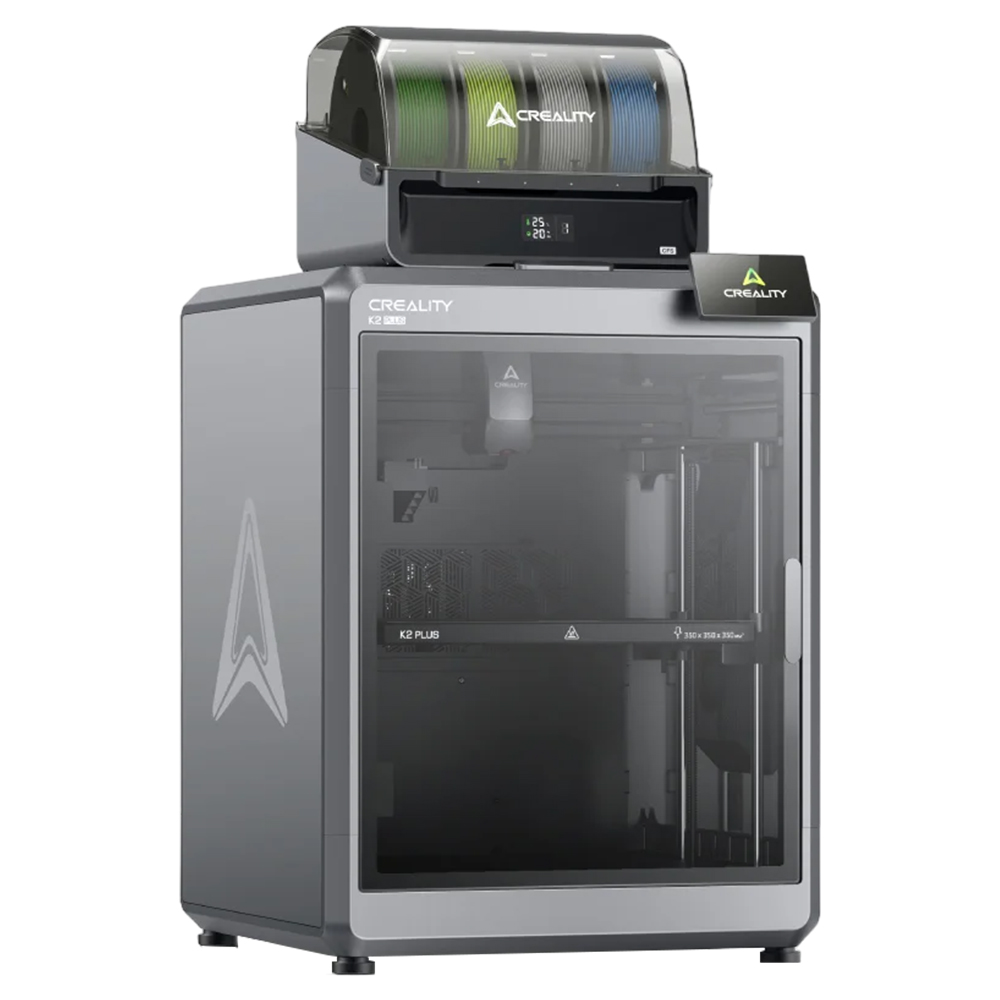
Build Volume: 350x350x350mm
Max Extruder Temperature: 300°C
In-Stock Materials: PLA (White, Black, Translucent, Red, Orange, Purple, Blue, Green, Tan), PETG (Translucent, White, Black), Fiber-Infused (CF) ABS (White and Black), Fiber-Infused (CF) Nylon
All Materials: PLA, ABS, PETG, TPU, PA (Nylon), PC, ASA, PET, Fiber-Infused polymers (Nylon, ABS, PLA, PETG), and more
Unique Properties
- Large build envelope
- Multi-material capabilities provided by "Automatic Material Switchers," 8 materials
Prusa XL

Build Volume: 360x360x360 mm
Max Extruder Temperature: 290°C
In-Stock Materials: PLA (White and Black), PETG (Translucent, White, Black), Fiber-Infused (CF) ABS (White and Black), Fiber-Infused (CF) Nylon
All Materials: PLA, ABS, PETG, TPU, PA (Nylon), PC, ASA, PET, PVA (Water-soluble), HIPS, and more
Unique Properties:
- Multi-material capabilities provided by 5 discrete tool-heads
- Our largest available FDM XY build volume
Voron 2.4

Build Volume: 350x 350x 350mm
Max Extruder Temperature: 350°C
In-Stock Materials: PLA (White and Black), PETG (Translucent, White, Black), Fiber-Infused (CF) ABS (White and Black), Fiber-Infused (CF) Nylon
All Materials: PLA, ABS, PETG, TPU, PA (Nylon), PC, ASA, PET, PVA (Water-soluble), HIPS, and more
Unique Properties
- Open-source platform allows us to retrofit this machine for alternative applications including but not limited to paste extrusion printing.
Filabot EX2

- This is not a 3D printer, but rather a filament extruder. With this machine, we have the ability to design custom thermoplastic filaments for use in our above printers.
Compatible Materials: PLA, ABS, PETG, TPU, PA (Nylon), PC, ASA, PET, Fiber-Infused polymers (Nylon, ABS, PLA, PETG), PVA (Water-soluble), PEEK, more.
Maximum Drive Force: 85in lbs (9.6Nm)
Output Filament Diameter: 1.75mm, 2.85mm, Custom (up to 4mm)
Unique Properties:
- Compound your own custom thermoplastic filaments for use in our 3D printers (or yours)
- Wide range of input materials
Materials
Common Materials:
PLA
PLA is a widely used thermoplastic known for its well-rounded properties, making it the default choice for FDM 3D printing. While not as durable as some other materials, PLA’s versatility and ease of use make it a go-to option for a wide range of applications.
PETG
PETG is a durable and versatile thermoplastic that offers excellent impact resistance and chemical resistance when compared to PLA. However, PETG is generally less rigid than PLA.
ASA
ASA is a high-performance thermoplastic known for its exceptional weather resistance and UV stability, making it ideal for outdoor applications. It combines excellent mechanical properties with resistance to environmental stressors, such as sunlight, heat, and moisture. ASA is commonly used in automotive parts, outdoor fixtures, and any application where long-term durability and appearance retention are crucial. ASA is generally regarded as similar to ABS, but is more easily printed
Fiber Infused Thermoplastics
All of our machines feature hardened extrusion systems to accommodate fiber-infused materials. Fiber infusion enhances a base polymer's (PLA, PETG, Nylon, etc) stiffness and typically it's printability. For the ultimate in part stiffness and durability, please see our "Reinforced FDM" option.
Less Common Materials:
ABS
ABS is a widely used thermoplastic known for its strong impact resistance, toughness, and durability. It’s ideal for creating functional parts that need to withstand physical stress, making it popular in automotive, consumer electronics, and appliance manufacturing. ABS is also well-suited for prototypes and end-use parts where strength and versatility are essential. However, it is no longer commonly used in 3D printing (supplanted by materials like ASA, and CF infused Nylon).
PEEK
PEEK is a high-performance thermoplastic known for its exceptional strength, chemical resistance, and thermal stability. It is widely used in demanding applications, such as aerospace, automotive, and medical devices, where durability and reliability are critical. PEEK’s ability to withstand high temperatures and harsh environments makes it ideal for creating components that require long-term performance under extreme conditions. In the context of 3D printing, it is often blended with chopped carbon fiber to increase it's stiffness and make it more readily printable.
Other Thermoplastics
FDM printing is generally compatible with many different types of thermoplastic. Please inquire with the TEAM lab if your desired polymer is not listed here.
Comparison to other printing technologies
Contrasted with Reinforced FDM
Reinforced FDM operates similarly to standard FDM printing but incorporates continuous strands of fiber filament to enhance stiffness and strength. However, unlike standard FDM, reinforced FDM does not support multi-material printing.
Contrasted with SLA or MSLA (Resin Printing)
Compared to SLA printing, FDM parts have limitations in shape complexity but are generally stronger and more cost-effective. Resin-based printing methods, such as SLA and MSLA, produce smooth, solid, non-porous parts, which are critical for applications requiring sterility and interaction with liquids.
Contrasted with Polyjet
FDM parts are significantly stronger and much more cost-effective than those produced with PolyJet printing. However, they are also less accurate and more limited in shape complexity. Additionally, PolyJet printing produces solid, non-porous parts, making it ideal for applications involving liquid interaction (but not typically sterile applications due to absence of sterilization protocol).
Contrasted with DLP (Microfluidic Printing)
Our DLP 3D printer is optimized for microfluidic applications, where precision, clarity, and smooth surface finish are essential. FDM printing is poorly suited for this purpose due to surface porosity, part opacity, and rougher finishes. These two technologies serve very different applications with minimal overlap.
Examples:

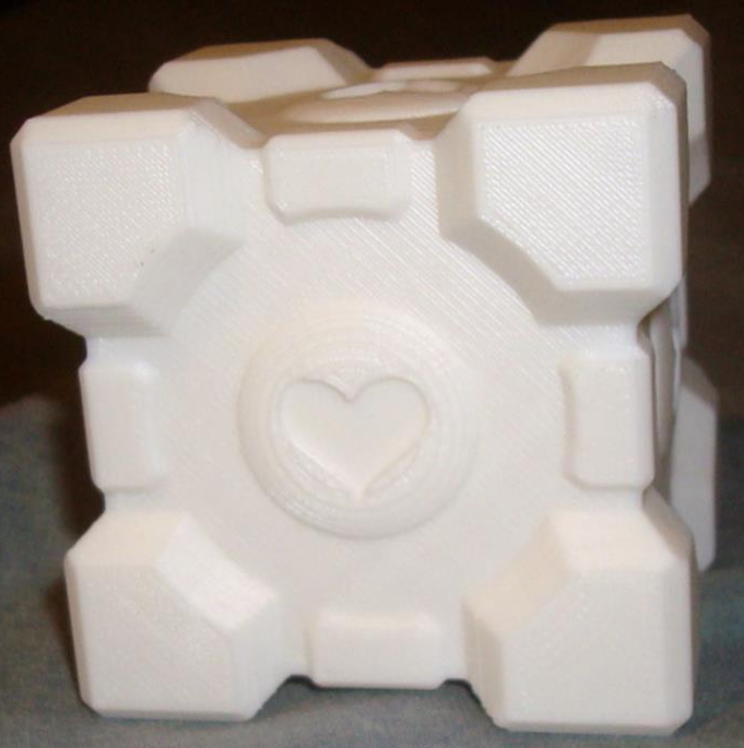


FDM Printing Gallery
Click here to view more example FDM prints.
Rates
- Note: We strongly recommend submitting a service request to obtain an accurate project cost estimate. Self-quoting can often lead to miscalculations
- Already have a quote from another vendor? Share it with us and we'll match or beat it.
We bill for time and materials while using our FDM printers. For time, we assess 0.5 hours of assisted time per-print tray plus an hourly rate for machine use. Maximizing tray capacity with your parts—whether identical or varied—significantly reduces per-unit part cost.
| Description | Internal | External | |
| Materials | Per-gram expense for all materials in-stock | $0.20/gram | $0.30/gram |
| Setup and Processing | 0.5 hours of our assisted rate ($119/hour) per tray (not object) | $59.50/tray | $80/tray |
| Hourly Use Rate | Expense per hour of machine use | $6/hour | $8/hour |
Estimating project cost should be left to TEAM, but here are some general project estimates that can guide in self-estimating:
| Relative Project Scale | Cost for First Batch of Parts, Typical Range | Cost for Additional Batch of Parts, Typical Range |
| Small | $60-$75 | $1-$20 |
| Medium | $75-$100 | $20-$40 |
| Large | $100-$150 | $40-$100 |
| Extra Large | $150+ | $100+ |
*All declared values at internal rates, NUD = university required "Non-University Differential" added for external.
Optional Post Processing Services
Epoxy Coating
If your FDM print necessitates a smooth surface finish, we can clad your prints in an epoxy coating to fill in surface defects. We stock, and use Smooth-On XTC-3D:
Pros of Epoxy Coating FDM Parts:
- Smooth, high-gloss surface finish
- Seals off surface porosity (to enhance compatibility with liquid applications)
- Paintable
Cons of Epoxy Coating FDM Parts:
- Alterations to the part's dimensional accuracy
- Additional cost (labor and materials)
Supports removal
Generally, we will do our best to remove supports as part of our basic service. However, if printing a very complicated part (with difficult to access supports, or a large volume of supports), we may assess additional time to cover the cost of support removal OR provide the part with supports for you, the client, to remove.
Threaded holes
Threads are generally not directly printed onto parts, but are instead added as a secondary process by way of tapping. Exceptions may occur where two bodies are designed to couple/decouple by way of coarse threads. Other (superior) techniques for adding threads involve using threaded inserts (usually brass), or capturing a nut; Both of these techniques result in much more durable threads than a printed part alone.
Important note regarding threaded features
- If your project incorporates threads, please make us aware so that we can coach you through the options and find the best fit for your application.
Direct-Printed Threads:

- Above Figure: Coarse Threads on Two Printed Bodies (via MatterHackers)
Strategies for adding threads as a post-processed feature:

- Above Figure: Different Techniques for Adding Threads to a Printed Part. Tapping, Threaded Insert, Captured Nut (via Formlabs)
Custom Material Manufacturing
We have the hardware necessary to manufacture our own custom blends of thermoplastic compatible with FDM printing. Further, our Voron 2.4 is an open-source design which allows us to consider other deposition processes (including but not limited to paste extrusion).
Preparing Files for Printing:
The team lab suggests two sets of files for each 3D printed part (where possible) – the original parametric model file (Solidworks/Inventor/Fusion360/etc), and a millimeter scale STL file (point-mesh file). Please include these files on your project request if possible.
For multi-material prints, we require one STL file for each material in a shared coordinate system. Please work with TEAM lab staff to ensure this constraint is satisfied.
Technical Details
Note
- FDM prints are generally regarded as low-precision when compared with other printing technologies; Prints can vary slightly from batch-to-batch, and Iteration and/or hand-finishing may be required to achieve desired fit between bodies.
Surface Finish
FDM prints will generally present to an informed individual as being printed; layer lines will be visible, and traces will be apparent along upward or downward facing faces. Our more advanced printing technologies (Resin Printing) will present with a much more consistent outward surface finish.
Support Material and Consequential Defects
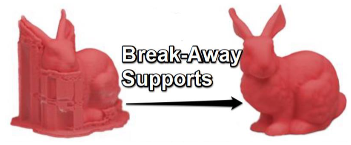
Overhanging features often necessitate the existence support structure (often made of the build material) which must be mechanically removed.
As FDM printing relies on adhesion to the build platform, or a previous layer below for the extruded filament to stick, some prints may require support structures where overhangs become too severe. Else, drooping, or failed printing may occur. These features are removed upon completion of the print, as a post-processing routine. In the instance that supports are needed, expect subtle print defects at locations where supports are used (rougher finish, mild drooping, etc). Through careful and intentional design, often times support structure can be avoided. Please see the figures below for an example of this property:
Layer thickness
We generally print our FDM parts at a layer thickness of 0.2mm unless otherwise asked.
Default infill and Shell Count
We generally print our FDM prints with a default shell count of 5 (to accommodate tapping operations) and 20% infill. If you need alternative settings, please define those upon project submission.
While thick walls result in stronger parts, too many “shells” can result in print defects that lead to poor surface finish, or warping.
- Actual wall thickness (dimension) is a multiple of the Nozzle diameter (typically 0.4mm), aka 1 “shell” thickness.
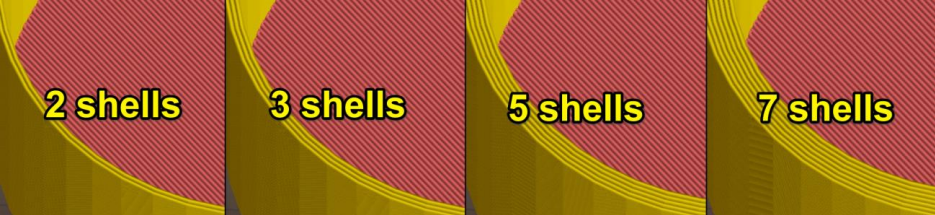
- Above Figure: Different Shell-Counts (via prusaprinters.org)
Minium Feature Size
Generally speaking, we advise a minimum feature size in excess of 1mm. This is not a hard-and-fast value; there are many variables that dictate if a feature can or cannot be realized via this technology.
- Note that we assess all prints for viability prior to starting as part of our general service to you; if we see a feature that is concerning, we will make direct and immediate contact to convey our concerns and help brainstorm a solution.
Thermoplastics
FDM printing is physically limited to thermoplastics; specifically, polymers that can be found on or made into a filament.
- The TEAM lab does offer custom filament extrusion as a service - inquire for more details
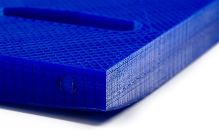
Hollow Prints
Parts derived from this technology are rarely solid; instead, they are generally created in a series of “shells” extending from the outside surface inward, coupled with an “infill” to provide bulk-support.
- This process is achieved within the printing/slicing software, not within CAD.
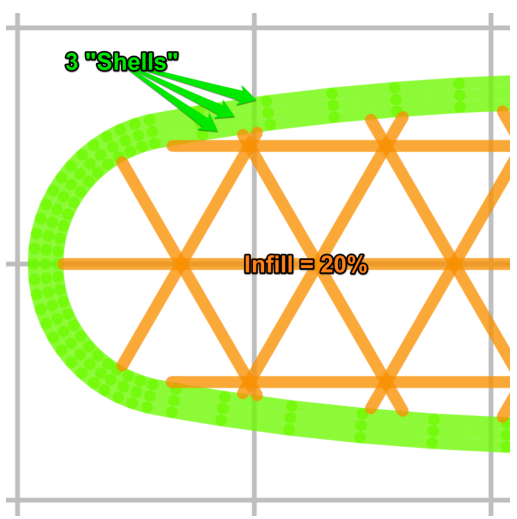
- Above Figure: Zoomed Depiction of 3D Print Cross-Section
Infill – This parameter adjusts how solid the interior of a part is. Low values (10-15%) reduce print time, and decrease weight with minimal impact on strength. High Values (15-25%) increase strength, but increase print time and can cause distortion. Very-High Values (25%+) can cause severe warping.

- Above Figure: Infill Percentages (via zx3d.com.au)

- Above Figure: Different Infill Patterns, all 30% fill (via Makerbot)
Distortion:
Due to thermal contraction, all FDM prints can be prone to distortion from their intended geometry. The following parameters are major factors in this process:
Aspect ratio
As a part becomes long, relative to its width, thermal distortion is more likely (bowing). Occasionally, this distortion can become so bad that prints fail due to the nozzle knocking against the print, causing it to detach from the built platform. It’s generally recommended to limit prints to a 5:1 length to width ratio (or smaller).
- Above Figure: Intended Part with Large Aspect Ratio (via Markforged)
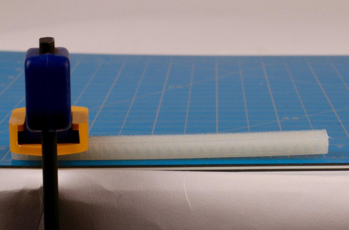
- Above Figure: Resultant Part is Warped (via Markforged)
Physical Size
Large prints are generally more likely to experience thermal distortion.
Sharp Corners
Sharp corners (~90 degrees) engaged with the print-surface can (in some cases) cause peeling/warping away from the build platform, where parts have a large footprint. To counteract this, we often recommend adding “Lilly pads” AKA “dog-ears” to the base of prints to encourage good adhesion. These features are then clipped off afterwards with little effect on the finished print. TEAM lab Tools and Techniques – FDM 3D Printing TEAM@UCD BME, Revised JUNE2018
- Above Figure: Warped Corner, no Lilly pad/Dog-ear (via Ultimaker)
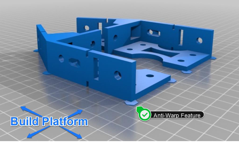
- Above Figure: Sacrificial Anti-Warp Features Added to a 3D Print underside (via Thingiverse)
Safety
All materials must meet approval by the TEAM lab prior to printing for the protection of our staff and hardware. If you wish to use something other than our standard offerings, we are open to the concept but please inquire for specifics!
Get Started
- Heard enough? Get started with a service request! Your request need-not be perfect, we can always revise it as we go. Just provide us with as much detail as is necessary.
- Feeling overwhelmed with the options? We don't blame you! We do a lot! Feel free to email us to set up a consultation. We're happy to chat via zoom, or in person (where we can review samples).